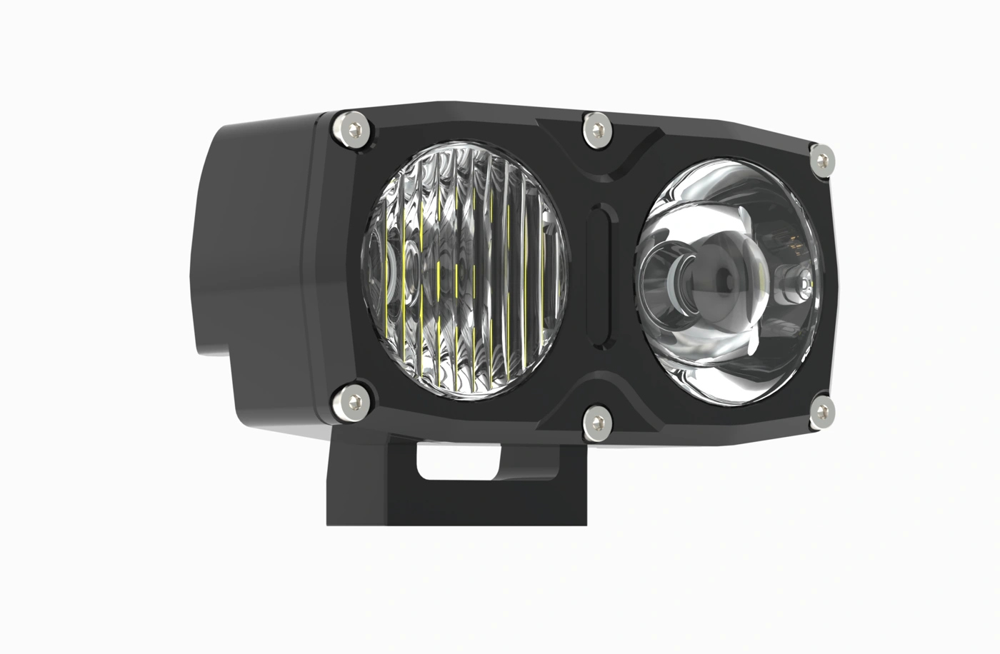

Z8i UHO · Wiring plan
464 W modeled · battery 13.8 V · ACC 13.8 V (tracks battery) · copper 105°C · one light / one circuit
Planning worksheet, not a factory pinout or approved harness. Toggle feed: fused ACC terminal bus, no main-feed splice. Relay contacts assumed closed. Some component losses are unmeasured and excluded. Verify component ratings, polarity, fuse coordination and loaded voltage before use.
| ID / connection | ft | AWG | A | Drop V |
|---|---|---|---|---|
| A · Battery + → main fuse F1 | 0.5 | 8 | 34.38 | 0.015 |
| B · Main fuse F1 → relay contact 30 | 1.5 | 8 | 34.38 | 0.046 |
| C · Relay contact 87 → positive pigtail | 2 | 8 | 34.38 | 0.061 |
| D · Negative pigtail → approved return | 4 | 8 | 34.38 | 0.122 |
| E · ACC bus / control fuse F2 → toggle switch | 2 | 14 | 0.17 | 0.001 |
| F · Toggle switch → relay coil + | 2 | 14 | 0.17 | 0.001 |
| G · Relay coil − → approved return | 1 | 14 | 0.17 | 0.001 |
| Factory + / − · fixed, each | 1 / 1 | 8 / 8 | 34.38 | 0.030 each |
| Battery V | Light V | Light A | Command % |
|---|---|---|---|
| 9.0 | 9.00 | 0.00 | 0.0 |
| 10.0 | 10.00 | 0.00 | 0.0 |
| 10.5 | 10.36 | 16.03 | 35.8 |
| 11.0 | 10.72 | 31.27 | 72.3 |
| 12.0 | 11.65 | 39.84 | 100.0 |
| 12.6 | 12.26 | 37.83 | 100.0 |
| 13.8 | 13.50 | 34.38 | 100.0 |
| 14.4 | 14.11 | 32.89 | 100.0 |
Hardware & rapid-dip basis
F1 main fuse: Not confirmed (70 A load-based candidate only).
F2 control fuse: Not confirmed. Coil input: 0.15 A at 12 V (entered assumption).
464.0 W protection basis. 11 V current: 42.2 A. Separate 9 V rapid-dip basis: 51.6 A. Relay/contact continuous planning target: ≥ 65 A before derating/inrush checks.
MCU command: 100% at ≥11 V; linear to 0% at 10 V. This is settled behavior, not a dip waveform. Standby current, optical output and dynamic recovery are not modeled.
Component path inputs, mΩ: F1 0, relay 0, other main connections 0, control path 0.
Install it once. Install it well.
Z8i UHO · Keep this checklist with your wiring plan · 2 / 2
A short checklist for a durable off-road installation. Follow the vehicle, light, connector and protection-device instructions for your exact hardware.
RECOMMENDED
- Keep runs short. Use the shortest practical protected route for positive and return wiring. Leave a small service loop for aiming and connector access; avoid coils of excess cable.
- Choose full-copper stranded automotive wire. Select insulation, gauge and terminals for current, length, temperature, fluids and exposure. Supplied wire size does not set the size of a long extension.
- Crimp with the correct tooling. Match the terminal to the conductor and insulation size. Use the specified die and strip length, inspect the finished crimp and gently check retention. Support the wire so vibration does not load the contact.
- Seal exposed joints. Use sealed automotive connectors and correctly sized adhesive-lined heat shrink where the joint design permits it. Apply controlled heat per its instructions; keep connector seals and mating faces clear.
- Protect and secure the route. Use temperature- and abrasion-rated sleeve or loom, grommets at metal pass-throughs, and suitable cushioned clips. Allow for steering, suspension and engine movement without tension or rubbing.
- Protect both circuits at their sources. Put F1 near the battery feed and F2 at the ACC bus terminal. Confirm fuse, holder, relay, connector and cable ratings together. Use the OEM-approved return path and terminal torque.
AVOID
- Heat and moving parts. Keep clear of exhausts, manifolds, turbos, belts, fans, driveshafts and moving suspension or steering parts. Check the full movement range. Loom is not permission to run against a hot surface.
- Sharp edges and pinch points. Do not trap wiring under brackets, seats or body panels, or stretch it across joints. Do not let cable ties crush insulation. Protect against stones, tire contact and pressure-wash exposure.
- CCA and unsuitable cable. Copper-clad aluminum has greater voltage drop than full copper of the same gauge. Avoid household solid-core wire and insulation unsuitable for the installed environment.
- Twist-and-tape or unsupported solder joints. Solder only where the terminal or OEM procedure calls for it. Excess solder can wick into strands and create a stiff flex point. Never use solder to rescue a poor crimp; support and seal an approved soldered joint.
- Unprotected taps and oversized fuses. Do not splice the toggle feed into the main power cable. Use the fused ACC terminal. Do not fit a larger fuse to cure repeated blowing or assume app dimming replaces circuit protection.
- Unverified grounds and terminal stacks. Do not bypass a battery-current sensor or use an arbitrary painted fastener as a return. Keep terminal connections accessible, protected and within the hardware maker’s stacking instructions.
BEFORE THE FIRST DRIVE
□ Isolate power using the vehicle’s procedure before wiring. Fit fuses after inspection. □ Confirm polarity, terminal markings, secure fasteners and connector locks.
□ Test under load: record battery voltage, voltage at the light and current. Compare with page 1. □ Check for abnormal heat, flicker, rubbing or a loose connection; stop and investigate if found.
□ Reinspect after the first rough-terrain outing and periodically thereafter. Keep the plan and component part numbers for service.
Need a second look? Send your plan, component part numbers and routing photos to info@racelights.com. More answers: racelights.com/fitment → Electrical → Search wiring FAQ.
Further guidance: TE Connectivity · automotive splice sealing; Ford · vehicle-specific harness routing. Example references do not replace your vehicle’s instructions.