
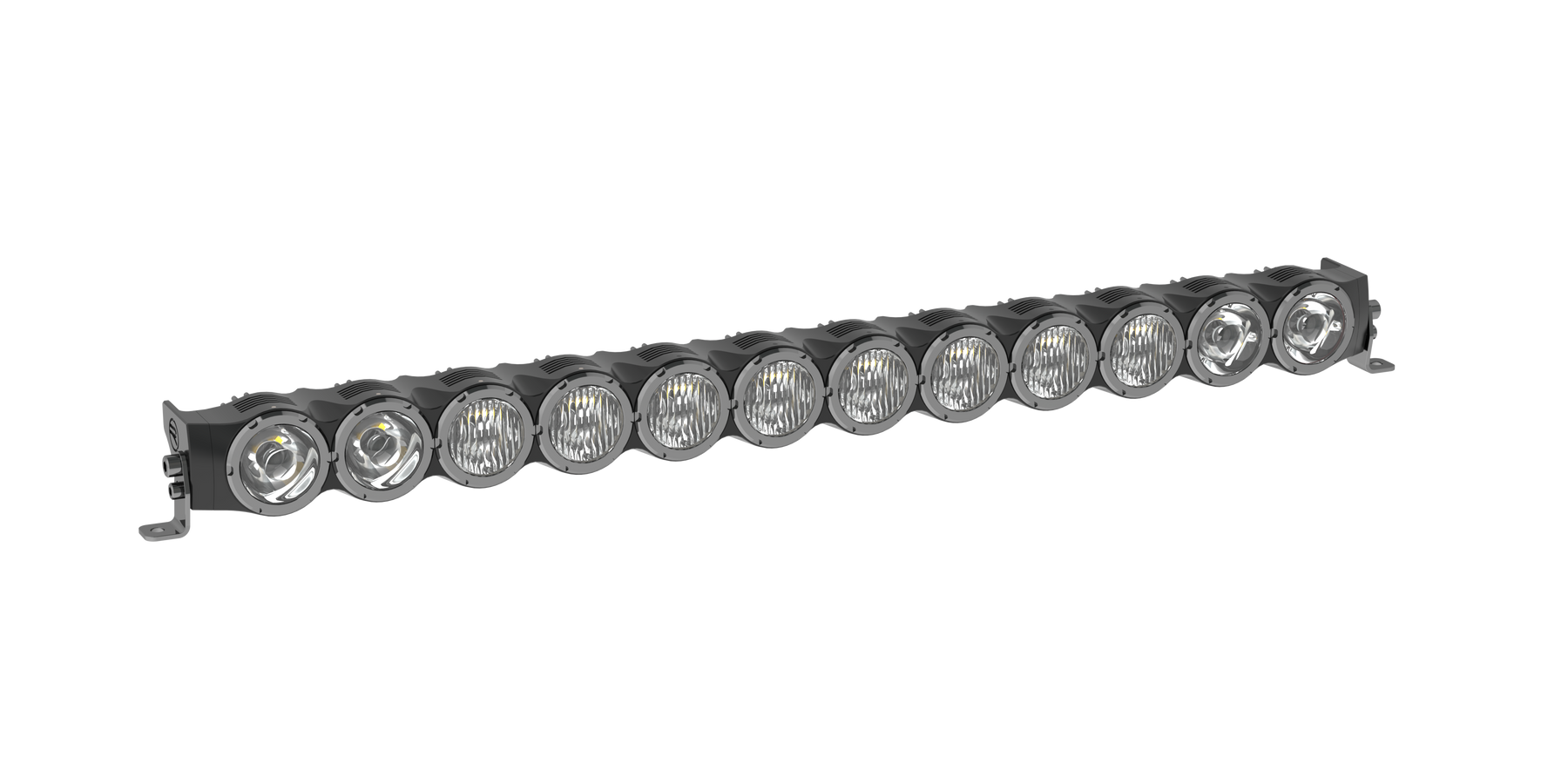
1. Before you start
- Match your light’s model and output designation to this guide. Check the supplied hardware and harness against your order.
- Dry-fit the light in its intended location. Verify room to aim it, plug and unplug the connector, route the cable, and reach the fasteners. Factory mounting points often require vehicle-specific brackets.
- Have the vehicle and bracket instructions, measuring tools, hardware, and electrical test equipment ready. Isolate power using the vehicle manufacturer’s procedure before working on the circuit.
2. Mount the light
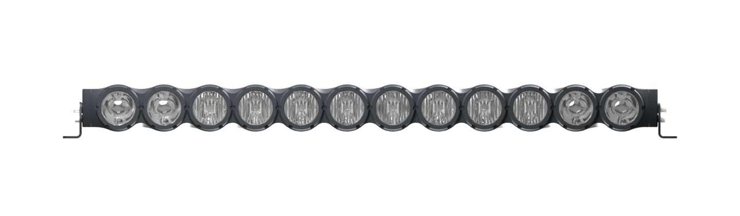
- End-cap mounting faces
- 800 mm (31.50″) apart
- Race bracket hole centers
- 833 mm (32.80″) apart · Ø 8.2 mm (0.32″)
- With Race mounting hardware
- 33.54 × 2.94 × 2.96″ W × H × D
- Compare the light’s end-cap faces with the inside spacing of your brackets. If using Race brackets, compare their base-hole centers with the vehicle mounting points.
- Secure the bracket to a suitable mounting point using the vehicle and bracket maker’s hardware and torque specifications. Contact Race if the light-side hardware specification is unclear.
- Seat the light in the bracket. Leave the aiming adjustment accessible and ensure the harness has room to move through the full aiming range.
3. Plan and connect power
- Calculated maximum at 12 V
- 46.4 A
- Factory pigtail
- 8 AWG · 12″ positive + 12″ return
- Main power
- Battery + → Main fuse → Relay contacts → Light +
- Light return
- Light − → Vehicle-approved return point
- Switch circuit
- ACC terminal → Control fuse → Toggle → Relay coil → Approved return
- Measure the actual routed positive and return lengths. Use the wiring wizard for loaded voltage drop and to review fuse, relay, wire, and connector ratings. The supplied gauge describes the factory connection. Size any extension for its own run and load.
- Follow the approved harness diagram. The main feed uses a fuse near the power source and a suitably rated relay. In the wizard’s relay example, the toggle controls the relay coil from a separate fused ACC circuit. Verify the pinout and polarity before connecting power.
- Use stranded copper automotive wire. Copper-clad aluminum has greater voltage drop for the same gauge and length. Secure the loom away from exhaust heat, sharp edges, and moving parts. Protect it at pass-throughs and support the harness near connectors.
4. Test and aim
- Verify polarity, connector engagement, fuse rating, and harness clearance before restoring power.
- In a clear area with the vehicle stationary, verify the light switches on and off. Measure battery and light input voltage under load and compare with the wiring plan.
- Open Race Tech and test brightness and the controls fitted to your build. Check RGBW backlights separately if equipped.
- Aim the light on level ground away from other people and traffic. Secure the aiming hardware, then recheck beam direction and harness clearance.
Troubleshooting
- No output
- Check the main fuse, the ACC trigger if used, the relay, and the return path. Check voltage at the light with the circuit switched on.
- Dimming or flicker
- Compare loaded voltage at the battery and at the light. Inspect connectors and returns for looseness and compare the actual route and conductor size with your wiring plan.
- Fuse blows or connector heats up
- Switch off and isolate power. Inspect for damaged wiring, poor connections, or a mismatched harness. Resolve the cause before replacing the fuse or restoring power.
Race, LLC · racelights.com/installation/z12i-vho-zenith-bar · Wiring wizard at racelights.com/wiring